
Computers have been around for years and gone a lot of advancements since it was first
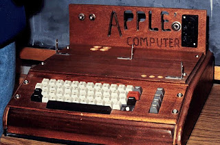
invented. From abacus to supercomputers, computers have changed humans way of living, how we work and communicate with other people. Computers ease our calculations and became an essential tool in industries and in our everyday living. The picture on the shows an Apple I sold as a do-it-yourself kit. Photo courtesy of http://www.computersciencelab.com/ComputerHistory/HistoryPt3.htm
Simple As Possible (SAP 1) is a type of computer architecture. According to WikiAnswers.com this type of computer architecture is used for academic purposes only. SAP-1 can only perform addition and subtraction not logical operations and these arithmetic operations are handled by the adder/subtracter unit. It has registers used for storing results and operands. The accumulator registers contains the result of the execution while the controller sequencer controls the operation of the computer. The output of the execution can be displayed at the Binary Display which has a 8-bit LEDs. The figure below is an architecture of SAP 1.

Figure 1: SAP - 1 Architecture
These are the SAP-1 architecture components: (1) Program Counter (PC) is a part of the control unit that counts form 0000 to 1111 or from 0 to F in Hex form. Its job is to send address to the memory. The address of the next instruction to be fetched is executed. (2) Input and MAR includes the address and switch registers. These switch registers which are part of the input unit will allow you to send an address bits to the RAM. (3) Static TTL RAM allows you to store data in memory before a computer or program runs. (4) Instruction Register (IR) is a part of a control unit. The contents of the instruction register are split into two nibbles. The Upper Nibble is a 2 state output that goes directly to the Controller Sequencer which controls the operation of the computer. The 12 wires carrying the word are called Control Bus. The Lower Nibble is a 3 state output that is directed onto the WBus. (5) Another component is the Accumulator, a buffer register that stores intermediate result of a computer operation. It has 2 outputs, the two-state output goes directly to the adder/subtracter and the three-state output goes to the WBus. (6) SAP-1 uses 2’s complement Adder/Subtracter. When Su is low and the sum out of the adder-subtracter is S=A+B. When Su is high, the difference appears A=A-B, and when Eu is high, the contents appear on the WBus. (7) B-Register is a buffer register used in arithmetic operations. (8) The accumulator contains the result of the executions and its content can be loaded into the Output Register. It is an interface to the outside system of the computer. (9) And the last component of the SAP-1 architecture is the Binary Display. It is a row of 8-bit LEDs where the result can be displayed.
The early microcomputers were not networked, did not have hard drives, and had less than 128,000 bytes of RAM. A typical MP3 song file today is 3,000,000 bytes in size (http://schoolcomputing.wikia.com/wiki/Early_Microcomputers), just like the SAP-1 architecture which has only 16 x 8 RAM. Aside from this, the RAM is a static Transistor-Transistor-Logic (TTL) which is also used in early microcomputers just like the Hewlett-Packard calculators. Kenbak-1 is another early computer that uses discrete TTL instead of microprocessor but still functions as a microcomputer.
Almost all computers have a lot in common and one of these is their computer organization which is based on the Von Neuman design. In computer organization, computers are usually broken into two parts, one which is the Memory that holds instructions and data and the other part is the Processing which is done by the central processing unit (CPU). The CPU reads instruction from the memory and applies necessary action to execute the instructions. The memory and the CPU can communicate with each other through the bus, an electronic pathway where data traverse. The bus of SAP-1 is 8-bit wide which is similar to Intel 8008 microprocessor which can access 8-bits of data in a single instruction.
Every computer has an instruction cycle or the fetch/execute cycle. The CPU gets an instruction from the memory (fetch) and then perform necessary action to the instruction (execute). After the instruction has been executed, it can either halt or fetch the next instruction. The SAP-1 is a synchronous circuit and executes one instruction at a time. Even early microcomputers follows the same fetch/execute instruction cycle.
When a user writes a program in a high-level language (HLL), the computer will not understand the program unless it is translated into a language that the computer understands. The HLL is translated into an equivalent assembly language which is then translated into the machine language where the instructions are strings of 0’s and 1’s which can also be easily understand by the computer. SAP-1 has five instructions which are all stored in the memory.
| Mnemonics | Opcode | Syntax | Operation |
| LDA | 0000 | LDA x | [ x ] –> ACC |
| ADD | 0001 | ADD x | [ x ] –> B ACC <– [ ACC ] + [ B ] |
| SUB | 0010 | SUB x | [ x ] –> B ACC <– [ ACC ] - [ B ] |
| OUT | 1110 | OUT | [ ACC ] –> 0 |
| HLT | 1111 | HLT | Disable |
The Mnemonics codes LDA (load into accumulator), ADD (add memory to accumulator), SUB (subtract memory from accumulator), OUT (display data) and HLT (stop execution) are all assembly language. On the other hand, opcode is the equivalent machine language of each mnemonic. Opcode identifies the instruction to be executed and each instruction has its unique opcode that the computer can handle. SAP-1 instruction cycle is broken into two cycles, the first is the fetch cycle which makes use of the PC, MAR, IR and RAM while the other one is the execution cycle. Fetch and execute cycles has three timing states each, T1, T2, and T3 for fetch cycle and T4, T5, and T6 for execute cycle. Each component of the SAP-1 has its own control lines which need to be activated and they can be either active high or active low. Activating the control lines enable each component to communicate with a particular device and the control inputs are handled by the control unit.
Thank u so much . . . This is very informative for a beginner . . . I appreciate your work . . can u please describe all the pins here . . . For eg. Cp, Ep, Lm(bar) . . . etc . . . .
ReplyDeletehow can i create new instruction like ora ana and jump in sap 1?
ReplyDeletehow can i increase the number of instruction set ,,like if i want to multiply then how can i add this instruction
ReplyDeleteit helped me gratly... :-)
ReplyDeletemy professor wants us to make an application out of this and I found it stupid. OMG. An application out of an application? Really?! I need help. What should I do!
ReplyDeletedo you have rtl code for complement for sap-1? thank you so much.
ReplyDeleteThanks.. Its so informative for the begginer..
ReplyDelete